
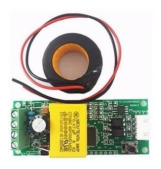
Sensor Corriente , Voltaje Y Energia, Salida Rs232, Arduino,
Información sobre el vendedor

MercadoLíder Gold
¡Es uno de los mejores del sitio!
- +1000
Ventas concretadas
Brinda buena atención


Descripción
AC digital display Multifunction Meter
A.Function
1. Ectrical parameter measurement function (voltage, current, active power, energy).
2. The reset function of energy key.
3. Store data when power off (store the accumulated energy before power off).
4. PC display function (display voltage, current, active power, energy).
5. Serial communication function (with TTL serial interface itself, can communicate with a variety of terminal through the pin board, read and set the parameters).
B. Front display and key
Figure 1 PC display diagram
I. Display Interface
PC display interface is formed by four windows, used to display the voltage, current, power, energy parameters, as shown in figure 1.
II. Display Format
1. Power: Test Range: 0 ~ 22kW
Within 0 ~ 10kW,the display format is 0.000 ~ 9.999;
Within 10 ~ 22kW, the display format is 10.00 ~ 22.00.
2. Energy: Test Range: 0 ~ 9999kWh
Within 0 ~ 10kWh,the display format is 0.000 ~ 9.999;
Within 10 ~ 100kWh,the display format is 10.00 ~ 99.99;
Within 100 ~ 1000kWh,the display format is 100.0 ~ 999.9;
1000 ~ 9999kWh and above,the display format is 1000 ~ 9999.
3. Voltage: Test Range: 80 ~ 260VAC
Display Format is 110.0 ~ 220.0.
4. Current: Test Range: 0 ~ 100A
Display Format is 00.00 ~ 99.99.
III.Key
There is a key on the panel, it can be used to reset energy, as shown in figure 2.
The method of reset energy: Long press the key for 5 seconds, then release the key. Short press the key again,then the energy data is cleared and quit the reset state, now the reset operation is completed.
C. Wiring diagram
Figure 2 Wiring diagram
The wiring of this module is divided into two parts: the voltage and current test input terminal wiring and the serial communication wiring, as shown in Figure2; according to the actual needs of the clients, with different TTL pinboard to achieve communicate with different terminals.
D. Display Interface
It display through PC or other terminals(need to programme),the PC display interface is shown as figure 1, the following are brief description of each parameter display:
1. Voltage Display
Measure and display the current power frequency network voltage.
2. Current display
Measure and display the current load (appliances) current. There is supplementary instruction that the current test value is from the beginning of 10mA , but this module belongs to high power test equipment, if you care about the mA level current testing accuracy, it is not be recommended.
3. Energy display
Measure and display the current accumulative power consumption. There is supplementary instruction that the minimum unit of the energy metering is 0.001kWh,which means it begins to accumulate from 1Wh,relatively speaking, the resolution is rather high, for the low-power(within 100W)load test, you can observe the accumulative process rather intuitively.
4. Power display
Measure and display the current load power. There is supplementary instruction that the power test value is from the beginning of 0.001kW , which means it begins to test from 1W, but this module belongs to high power test equipment, if you have the requirement of the testing within 1W, it is not be recommended.
E. Serial communication
This module is equipped with TTL serial data communication interface, you can read and set the relevant parameters via the serial port; but if you want to communicate with a device which has USB or RS232 (such as computer), you need to be equipped with different TTL pin board (USB communication needs to be equipped with TTL to USB pinboard; RS232 communication needs to be equipped with TTL to RS232 pin board), the specific connection type as shown in Figure 2. In the below table are the communication protocols of this module:
NO. function Head Data1- Data5 Sum
1 voltage B0 C0 A8 01 01 00 (Computer sends a request to read the voltage value) 1A
A0 00 E6 02 00 00 (Meter reply the voltage value is 230.2V) 88
2 current B1 C0 A8 01 01 00 (Computer sends a request to read the current value) 1B
A1 00 11 20 00 00 (Meter reply the current value is 17.32A) D2
3 Active power B2 C0 A8 01 01 00 (Computer sends a request to read the active power value) 1C
A2 08 98 00 00 00 (Meter reply the active power value is 2200w) 42
4 Read energy B3 C0 A8 01 01 00 (Computer sends a request to read the energy value) 1D
A3 01 86 9f 00 00 (Meter reply the energy value is 99999wh) C9
5 Set the module address B4 C0 A8 01 01 00 (Computer sends a request to set the address, the address is 192.168.1.1) 1E
A4 00 00 00 00 00 (Meter reply the address was successfully set) A4
6 Set the power alarm threshold B5 C0 A8 01 01 14 (computer sends a request to set a power alarm threshold) 33
A5 00 00 00 00 00 (Meter reply the power alarm threshold was successfully set) A5
Illustration of the communication protocol example:
1.Set the communication address: 192.168.1.1
Send command: B4 C0 A8 01 01 00 1E
Reply data: A4 00 00 00 00 00 A4
Note: The above example illustrate that setting the communication address as 192.168.1.1 (the user can set their own address based on their preferences and needs), sending commands and replying data automatically are as shown above, the data are expressed in hexadecimal; the last byte of the sending and replying data are 1E and A4, belong to cumulative sum. At sending commands: B4 + C0 + A8 + 01 + 01 + 00 = 21E (use the hexadecimal addition), the cumulative sum data is 21E, take the last two bytes 1E to be used the cumulative sum data in sending commands; data in reply: A4 + 00 + 00 + 00 + 00 + 00 = A4 (use the hexadecimal addition),the cumulative sum data is A4,which is the cumulative sum data in reply.
The explanation ofthe cumulative sum is now finished, the following parameter examples are the same as this, there is no explanation any more.
2. Set the power alarm threshold:20 KW
Send command: B5 C0 A8 01 01 14 33
Reply data: A5 00 00 00 00 00 A5
Note: 14 in the sending commandis the alarm value (14 is a hexadecimal data representation, which converted to decimal is 20). What you should note is the power alarm value of this module is based on KW units, which means the minimum alarm value is 1KW, the maximum value is 22KW.
3.Read the current voltage
Send command: B0 C0 A8 01 01 00 1A
Reply data: A0 00 E6 02 00 00 88
Note: Reply voltage data is D1D2D3 = 00 E6 02,00 E6 representthe integer-bit of the voltage, 02 representthe decimal of the voltage, the decimal is one digit,converts 00 E6 to decimal is 230; converts 02 to decimal is 2, so the current voltage value is 230.2V.
4.Read the current current
Sendcommand: B1 C0 A8 01 01 00 1B
Reply data: A1 00 11 20 00 00 D2
Note: Reply current data is D2D3 = 11 20,11 represent the integer-bit of the current, 20 represent the decimal of the current, the current decimal is two digits,converts 11 to decimal is 17; converts 20 to decimal is 32, so the current current value is 17.32 A.
5.Read the current power
Sendcommand: B2 C0 A8 01 01 00 1C
Reply data: A2 08 98 00 00 00 42
Note: Reply power data is D1D2 = 08 98,converts 08 98 to decimal is 2200, so the current voltage value is 2200W.
6.Read the energy
Send command: B3 C0 A8 01 01 00 1D
Reply data: A3 01 86 9F 00 00 C9
Note: Reply energy data is D1D2D3 = 01 86 9F, converts 01 86 9F to decimal is 99999, so the accumulated power is 99999Wh.
F. Illustration of the communication
1. Connect hard wire according to the wiring diagram in figure 2.
2. After connect the wire, please choose the communication port, this module’s upper computer software support communication port: COM2\COM3\COM4, you can check through device manager, if it is not the above communication port, you should amend it through port.
G. Precautions
1. This module is suitable for indoor, please do not use outdoor.
2. Applied load should not exceed the rated power.
3. Wiring order can’t be wrong.
H. Specification parameters
1. Working voltage: 80 ~ 260VAC
2. Test voltage: 80 ~ 260VAC
3. Rated power:100A/22000W
4. Operating frequency: 45-65Hz
5. Measurement accuracy: 1.0 grade
Envios y Entregas
- Se hacen despachos por pagar a otras ciudades
- Entregas por mano solo se hacen de lunes a sábado en el centro de Viña en la
Mañana a las 11:30.
- Despachos para compras antes de las 11.00 se hacen en el dia
Notas
- Si está publicado es por que hay stock
- Si después de 7 días no se ha realizado la compra, se presume que ésta no se
efectuará y se cancelara la venta
- Cualquier pregunta, no dude en consultar
Preguntas y respuestas
Nadie ha hecho preguntas todavía.
¡Haz la primera!